Week 3: Programming Servo with Arduino Summary In...
Read MoreIn Week 3, students will learn how to control a servo motor using straightforward code. This week will emphasize understanding how to position a servo to specific angles and timing the movements.
- Active participation in discussions and hands-on activities.
- Timely completion of assignments.
- Demonstrated understanding of basic servo control.
- Adherence to safety protocols.
- Respectful collaboration with peers.
- Module 1: Introduction to Servo Programming
- Module 2: Connecting a Servo to Arduino
- Module 3: Basic Servo Control Code
- Module 4: Practice Session
- Module 5: Questions
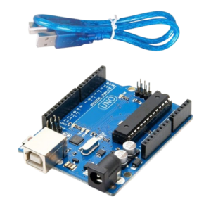
1. Arduino Board
- Function in Project: Acts as the main microcontroller to run the program and control the LED.
- Other Real-life Uses: Can be used in robotics, home automation, weather stations, and many other DIY electronic projects.
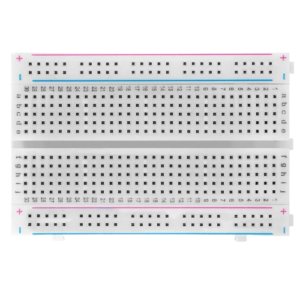
2. Breadboard
- Function in Project: Provides a platform to build and test circuits without soldering.
- Other Real-life Uses: Useful for prototyping circuits in electronics development and for educational purposes.
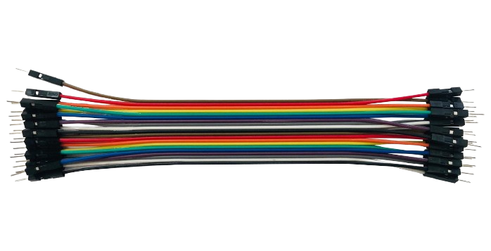
3. Jumper Wires
- Function in Project: Connect different components on the breadboard and to the Arduino.
- Other Real-life Uses: Used for making temporary connections in testing and prototyping electronic circuits.
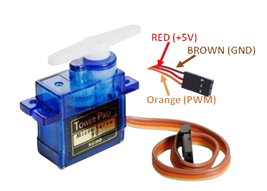
4. Servo Motor
- Function in Project: A small motor that moves to specific angles based on the code uploaded to the Arduino.
- Other Real-life Uses: Used in robotics for joint movements, in RC vehicles for steering, in automation systems, and in camera gimbals for stabilization.

5. Computers with Arduino IDE Installed
- Function in Project: Used to write, compile, and upload programs to the Arduino board.
- Other Real-life Uses: Computers with development environments are essential for programming, software development, and interfacing with various hardware devices.
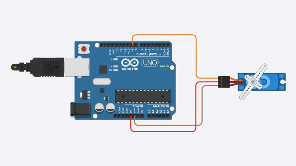
Servo Connections:
- Red wire: Connect to the 5V pin on the Arduino.
- Black/brown wire: Connect to the GND pin on the Arduino.
- Yellow/white wire: Connect to digital pin 9 on the Arduino.
Write and upload simple Arduino code to control the servo’s position.
#include <Servo.h>
// Define the servo pin
int servoPin = 9;
Servo myServo;

void setup() {
  // Attach the servo to pin 9
  myServo.attach(servoPin);
  // Initialize serial communication for debugging
  Serial.begin(9600);
}

void loop() {
  // Move the servo to 0 degrees
  myServo.write(0);
  delay(3000); // Wait for 3 seconds

  // Move the servo to 180 degrees
  myServo.write(180);
  delay(3000); // Wait for 3 seconds
}
Activity: Experiment with modifying the code to observe different behaviors.
Change Angles: Adjust the myServo.write() values to positions other than 0 and 180 degrees (e.g., 90 degrees) and observe the results.
Modify Delays: Change the delay() values to make the servo pause for different lengths of time (e.g., 1000ms, 5000ms).